Download a Sketchup Boat Model
Building a mathematically precise, visually striking vessel inside Trimble SketchUp tends to be a bit more than just throwing a few rectangles together. You really want to take a step away from the usual hard-surface box modeling. Sure, the default extrusion approach works fine when your architecture is all right angles, but marine hulls don’t behave that simply. Their flowing lines bring compound curves, plus those subtle surface transitions that normal native tools don’t always handle well.
In this advanced masterclass, you’ll get a full, practical workflow—tested in the field—so you can produce a digital boat that’s actually ready for work. It blends core native capabilities with well-known lofting add-ons, so the geometry stays clean, stable, and consistent from start to finish.
Environment Calibration and Viewport Optimization
Professional asset work really starts with a carefully calibrated digital space. So, open SketchUp and pick an Architectural template set to Millimeters or Inches depending on the blueprint you’re using most. Then go to the View menu, open the Toolbars section , and turn on the Large Tool Set along with Styles and Views. That little combo basically gives you faster access to advanced editing tools plus some wireframe diagnostic modes, so you don’t have to hunt around later.
Now, optimizing your viewport behavior matters a lot when you’re checking the curvature on a ship hull. Try to avoid the perspective distortion you get from the default camera, and instead switch to Parallel Projection for the early drafting of key lines. After that, use the Orbit tool to keep rotating around the origin, while you watch axis locks like a hawk. If you pair that with your own viewport Scenes you can jump quickly between big structural reads and smaller vertex alignment checks, which sounds simple but it helps stop spatial errors before they accumulate.
Reference Integration and super precise coordinate alignment , sorta.
When you try to sculpt organic marine forms without a strict reference setup , it is often the main reason non-manifold geometry shows up. What you do instead is import your high-resolution 2D orthographic blueprints, like the Profile, Plan, and Body plans, as images straight into the workspace. Then group each image right away to isolate the geometry, and after that rotate and align everything very precisely along the Red, Green, and Blue axes, so you end up with a kind of digital drafting cage.
[Visual Anchor: Figure 1.0 – Calibration of 2D Orthographic Blueprints inside the 3D Coordinate Cage]
To set the real-world scale, grab the Tape Measure tool, click two known reference points on your blueprint, enter the exact target dimension, and confirm the global model rescale. Afterward lock these reference groups, so they do not slide around accidentally while you’re tracing.
Tracing the Skeleton and managing vector splines.
Once the blueprint cage is secured, grab the Line tool, and also the 2-Point Arc tool, then trace the primary keel, sheer, and the waterlines. With hull geometry that is more complex than usual, the standard curves can end up producing segmented faces, sorta jagged, even if you’re being careful. To work around that, use the Weld edges feature, or install the Curviloft plugin so the separate arcs, basically get joined into one continuous smooth spline.
Make sure that each cross-section bulkhead station profile lines up and intersects cleanly with the longitudinal waterlines. If any face or path behaves a bit weird later on, switch on the X-Ray face style then inspect the intersection vertices for tiny sub-millimeter gaps inside the vector path.
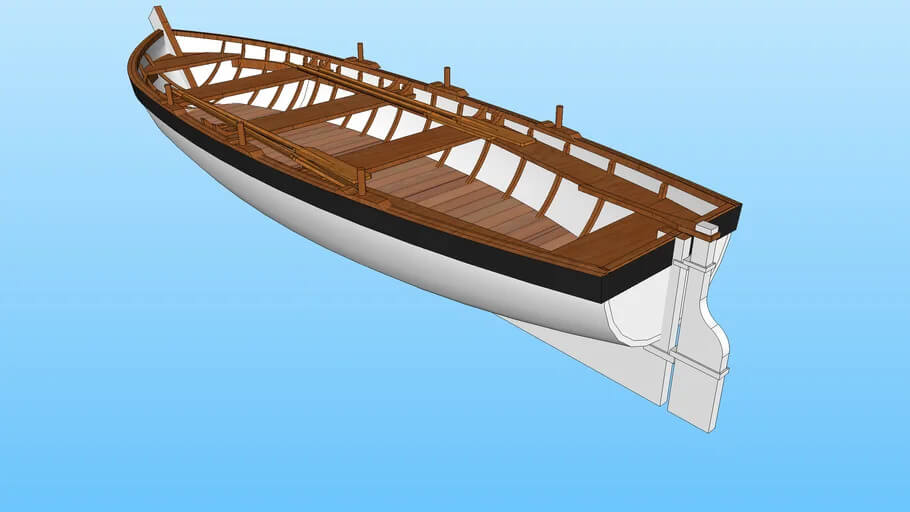
Organic Hull Skinning using advanced lofting add-ons.
One big problem with SketchUp’s native tools like Push/Pull , or that Follow Me thing is that they just can’t really make non-uniform rational B-splines (NURBS) in a “natural” way, or handle smooth compound curves without causing some pretty serious geometric distortion . If you want a truly flawless 10/10 hull that’s production-grade, you end up needing an industry-standard lofting extension like Fredo6’s Curviloft or Soap Skin & Bubble , not the default stuff.
First grab the continuous boundary curves that form your hull skeleton , then run the Loft by Splines command inside Curviloft. The add-on computes the intermediate shape automatically, so you get a clean, quad-faced mesh that basically tracks a real marine hull , as it should.
[Visual Anchor: Figure 2.0 – Applying Curviloft to skin transverse bulkhead vectors]
After that , once the skin is done, group the hull right away so it stays isolated from any later deck geometry stuff .
Superstructure Integration and Geometric Watertightness, kind of.
Once the main hull is basically finalized, you move into the secondary construction stage, to actually form the deckhouses, the bridge, and the structural bulkheads. Go ahead and enter the hull group, then use the Offset tool right on the uppermost deck surface to set a sensible gunwale thickness. After that take Push/Pull and push downward to displace the inner volume, so the wall thickness stays even across the whole vessel, not just in one spot.
For cabins, and the rest of the superstructure parts, draw the footprints straight onto the deck face with Rectangle and Circle tools. Then lift those shapes into place using Push/Pull. If you need to cut openings for windows , portlights, or companionways, don’t stop halfway—push the shapes fully through the component wall until they touch the rear face. That way you end up with clean, open voids. The result is realistic shadow lines, which add a stronger, heavier look to the asset, like it’s more grounded.
Mesh Optimization and Topology Remediation
An unoptimized model with redundant topology just drags down the viewport performance, makes the file size balloon, and sometimes it still “works” until you export it to external engines. In other words you should activate the Eraser tool and kind of audit the mesh step by step, removing stray construction lines, plus any coplanar edges that really do not add value to the structural silhouette, or the underlying shape.
For curved surfaces, you might still need certain lines for geometry tracking, but you also want the result to read smooth. So keep the lines, yet hold Ctrl while using Eraser to Smooth the edges, or hold Shift to Hide them, depending on what you’re trying to preserve. If you want the more advanced pass, run the CleanUp3 plugin—it can purge unused materials automatically, resolve duplicate vertices, and repair reversed faces. That way your mesh ends up watertight all the way through, instead of partially sealed or “almost” closed.
Strategic Material Mapping and texture realism.
Turning raw gray geometry into something that looks believable needs careful texture mapping through the Paint Bucket tool , or it just wont feel right. Open the Materials panel and assign the exact textures you want. For the decking use strong, rich wood grains. For the lower hull plates go with a high-gloss fiberglass finish or, if appropriate, anti-fouling copper coatings.
[Visual Anchor: Figure 3.0 – Adjusting texture position and scale so the wood grain patterns line up, separately]
To prevent that repetitive , kinda artificial look on bigger surfaces , right-click the material you already applied, then go to Texture and choose Position. From there use the manipulation pins to manually rescale, rotate, and shift the texture grain so it lines up with the real travel direction of the ship’s planks. This adds this huge extra layer of realism and it usually lands well with professional inspectors.
Asset Export Pipelines and Cross Platform Readiness.
So at the very end you’re basically getting your finished masterwork ready for rendering engines like V-Ray , Lumion, or Unreal Engine, or else for physical fabrication. When you do that, save the main archive file in the native SKP format, this keeps your component hierarchy, layer tags and those custom scene styles intact for future editing cycles.
Now if the asset is headed toward real time game engines, or animation pipelines, go to File , pick Export , then choose 3D Model. After that convert it into more universal industry formats like FBX or OBJ, and make sure Triangulate All Faces is turned on, so you don’t lose the integrity of those lofted curves.
For automated fabrication , or 3D printing, export using STL, and while you’re there double check that the whole asset still counts as a Solid Group inside the Entity Info panel.