Views: 0
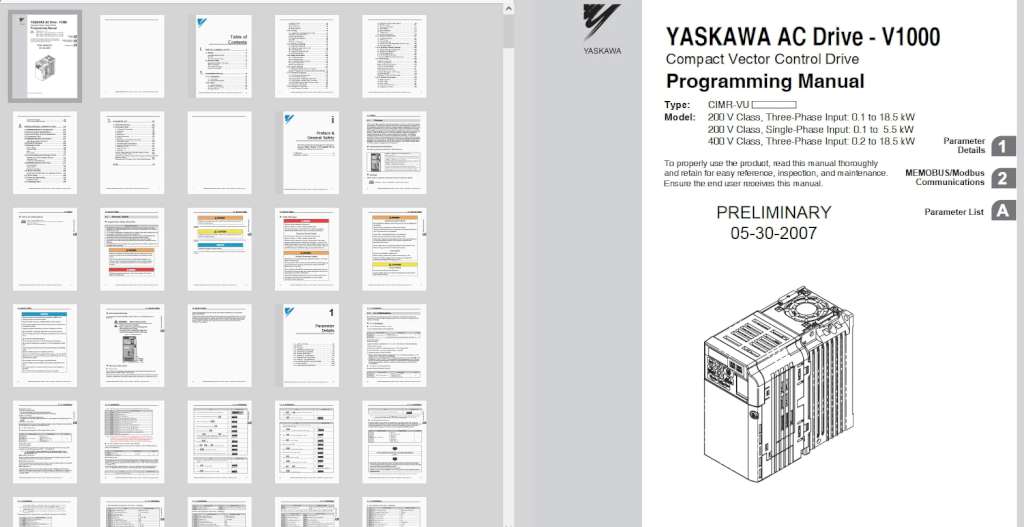
About the Yaskawa v1000 User Manual
There is a 388-page PDF of the Yaskawa V1000 user manual. On that page, there is usage information for each section of the product. You download one file and read 388 pages. You can download it from our site with a total file size of 10.9 MB. Once you download the file, you can view it through Adobe Acrobat Reader or any web browser. You typically will be able to find it in the Downloads folder if you download the file on your desktop computer. On a mobile phone, you need to go open the file application and click the Downloads icon if you downloaded it. This is where the PDF document you downloaded will be.
The document covers the following topics:

Table of Contents
| PREFACE & GENERAL SAFETY | 9 |
| i.1 Preface | 10 |
| Applicable Documentation. | 10 |
| Symbols | 10 |
| Terms and Abbreviations. | 11 |
| i.2 General Safety | 12 |
| Supplemental Safety Information | 12 |
| Safety Messages | 14 |
| Drive Label Warnings. | 17 |
| Warranty Information. | 17 |
| PARAMETER DETAILS. | 19 |
| 1.1 A: Initialization | 20 |
| A1: Initialization. | 20 |
| A2: Preferred Parameters. | 34 |
| 1.2 b: Setup. | 36 |
| b1: Mode of Operation | 36 |
| b2: DC Injection Braking | 50 |
| b3: Speed Search | 52 |
| 4 YASKAWA ELECTRIC SIEP C710606 10A YASKAWA AC Drive-V1000 PRELIM. Programming Manual | |
| b4: Delay Timers | 62 |
| b5: PID Control. | 63 |
| b6: Dwell Function | 75 |
| b8: Energy Saving | 75 |
| 1.3 C: Tuning | 78 |
| C1: Acceleration and Deceleration Times. | 78 |
| C2: S-Curve Characteristics | 81 |
| C3: Slip Compensation | 83 |
| C4: Torque Compensation. | 85 |
| C5: ASR | 86 |
| C6: Carrier Frequency | 88 |
| 1.4 d: Reference Settings. | 93 |
| d1: Frequency Reference. | 94 |
| d2: Frequency Upper/Lower Limits. | 98 |
| d3: Jump Frequency. | 100 |
| d4: Frequency Reference Hold | 101 |
| d7: Offset Frequencies | 106 |
| 1.5 E: Motor Parameters. | 108 |
| E1: V/f Characteristics | 108 |
| E2: Motor Parameters | 115 |
| E3: V/f Characteristics for Motor 2. | 118 |
| E4: Motor 2 Parameters. | 120 |
| E5: PM Motor Settings | 124 |
| 1.6 F: Option Settings | 127 |
| F1: Settings for Simple PG with V/f Control | 127 |
| F6 and F7: Serial Communications Option Card Settings | 128 |
| 1.7 H: Terminal Functions. | 136 |
| H1: Multi-Function Contact Inputs. | 136 |
| H2: Multi-Function Outputs | 160 |
| H3: Multi-Function Analog Input Terminals | 176 |
| H4: Multi-Function Analog Output Terminals. | 184 |
| H5: MEMOBUS/Modbus Serial Communication | 185 |
| H6: Pulse Train Input/Output. | 188 |
| 1.8 L: Protection Functions | 191 |
| L1: Motor Protection Functions | 191 |
| YASKAWA ELECTRIC SIEP C710606 10A YASKAWA AC Drive-V1000 PRELIM. Programming Manual 5 | |
| L2: Momentary Power Loss Ridethru | 198 |
| L3: Stall Prevention. | 201 |
| L4: Frequency Detection. | 211 |
| L5: Fault Restart | 213 |
| L6: Torque Detection | 214 |
| L7: Torque Limit | 217 |
| L8: Hardware Protection. | 218 |
| 1.9 n: Special Adjustments | 221 |
| n1: Hunting Prevention. | 221 |
| n2: AFR Tuning | 222 |
| n3: High Slip Braking | 222 |
| n6: Line-to-Line Motor Resistance Online Tuning. | 225 |
| n8: PM Motor Control | 225 |
| 1.10 o: Operator Related Settings | 228 |
| o1: Display Settings and Selections | 228 |
| o2: Operator Key Selections. | 230 |
| o4: Maintenance Period. | 234 |
| q: DriveWorksEZ Parameters. | 237 |
| r: DriveWorksEZ Connection Parameters | 237 |
| 1.11 Auto-Tuning. | 238 |
| Types of Auto-Tuning | 238 |
| Auto-Tuning Selection | 239 |
| Before Auto-Tuning the Drive. | 240 |
| Auto-Tuning Fault Codes | 241 |
| Performing Auto-Tuning. | 241 |
| Motor Data for Auto-Tuning. | 244 |
| Precision Settings for Auto-Tuning. | 245 |
| No-Load Operation. | 245 |
| Operating with the Load Connected | 247 |
| 1.12 U: Monitor Parameters | 248 |
| U1: Status Monitors | 248 |
| U2: Fault Trace | 251 |
| U3: Fault History | 252 |
| U4: Maintenance Monitors | 254 |
| U5: Application Monitors. | 256 |
| U6: Control Monitors | 257 |
| U8: DriveWorksEZ Monitors | 258 |
| MEMOBUS/MODBUS COMMUNICATIONS | 259 |
| 2.1 MEMOBUS/Modbus Configuration | 260 |
| 2.2 Communication Specifications. | 261 |
| 2.3 Communication Terminal Resistance | 262 |
| 2.4 Connecting a PLC | 263 |
| 2.5 MEMOBUS/Modbus Parameters. | 264 |
| MEMOBUS/Modbus Parameters | 264 |
| 2.6 Related Parameters | 268 |
| 2.7 Message Format. | 269 |
| Slave Address. | 269 |
| Function Code. | 269 |
| Data. | 270 |
| Error Check | 270 |
| 2.8 Command/Response Message Format | 271 |
| Reading Drive Memory Register Contents | 271 |
| Loop Back Test | 272 |
| Writing to Multiple Registers | 272 |
| 2.9 MEMOBUS/Modbus Data Table. | 274 |
| Command Data | 274 |
| Monitor Data | 275 |
| Broadcast Messages | 279 |
| 2.10 Enter Command. | 280 |
| ENTER Command Settings when Upgrading the Drive | 280 |
| 2.11 Error Codes | 282 |
| 2.12 Slave Not Responding | 283 |
| Application Notes | 283 |
| 2.13 Self-Diagnostics. | 284 |
| PARAMETER LIST. | 285 |
| 3.1 Parameter Groups. | 286 |
| 3.2 Parameter Table. | 287 |
| A: Initialization Parameters | 287 |
| b: Application. | 288 |
| C: Tuning | 295 |
| d: References. | 300 |
| E: Motor Parameters | 305 |
| F: Options | 311 |
| H Parameters: Multi-Function Terminals | 315 |
| L: Protection Function | 327 |
| n: Advanced Performance Set-Up. | 340 |
| o: Operator Related Parameters | 344 |
| r: DWEZ Parameters | 347 |
| T: Motor Tuning | 349 |
| U: Monitors | 350 |
| Control Mode Dependent Parameter Default Values | 361 |
| V/f Pattern Default Values | 363 |
| Default Settings Determined by Drive Capacity (o2-04) and ND/HD | |
| Selection (C6-01). | 364 |
| Parameters that Change with the Motor Code Selection | 373 |
| INDEX | 379 |

